ESP32 Audio Spectrum Analyzer

I wanted to build a RGB LED Strip based Audio Spectrum analyser , I looked at various projects and they belong to two categories, one with a MSGEQ7 Spectrum Analyzer chip and one with pure software FFT. I chose to go with pure Software FFT project, the one that had all the features and performance I was looking for was from

https://github.com/donnersm/FFT_ESP32_Analyzer

When this code detects silence it automatically Switches to a Fire Screen saver, which was really cool. This got me thinking to see if I can add other effects to this project.

https://github.com/marcmerlin/FastLED_NeoMatrix_SmartMatrix_LEDMatrix_GFX_Demos

https://github.com/Intrinsically-Sublime/esp8266-fastled-webserver

The above projects had a bunch of screen effects that Integrated.

I also wanted much better control over things like filters , timing and effects , So I decided to port a webserver that I had developed for another project to this.

This project has the following Features.

  1. FFT Based 32 Band Audio Spectrum analyser that drives a 16×32 ws2812b based Serial LED Matrix .
  2. Has 11 Spectrum Effects and 30 Screen Saver Effects.
  3. Can be controlled from Mobile Phone in AP mode or you can connect to your home WiFi and use it from the browser / app.
  4. Update the firmware over http OTA.

When the Device is booted it will start in AP mode supporting a Captive portal.

In your Mobile phone scan for Wifi Networks and you will see GW-DAM-XX:XX:XX:XX AP

Connect to it ,It should automatically open the following page. If it does not, open the web browser and enter http://8.8.4.4

Here you can enter your home WiFi SSID and Password or if you can directly click on
Led Config link at the bottom and configure the display.

In this screen you can control all the features of the Display.

You can see a demo video here

GitHub Code Links

Modified Code.
https://github.com/RasaAudio/gSpectrumAnalyzer

Original Code for Spectrum Display From https://www.facebook.com/TheelectronicEngineer

Original Code for Effects from https://github.com/marcmerlin/FastLED_NeoMatrix_SmartMatrix_LEDMatrix_GFX_Demos
https://github.com/Intrinsically-Sublime/esp8266-fastled-webserver
and Uses Adafruit GFX libraries

I have modified the neomatrix_config.h file for my display you should be able to modify it for your exact led matrix layout and everything else it should work as expected.

Build Instructions:

Download the code from
https://github.com/SunRays979/gSpectrumAnalyzer
open the ino file in arduino-1.8.19 (others might work too).
Install the following libraries using the library manager.
ESP32_HUB75_LED_MATRIX_PANEL_DMA_Display
Adafruit_NeoMatrix
EasyButton
arduinoFFT
Adafruit_BusIO
Adafruit_GFX_Library
FastLED
Framebuffer_GFX
FastLED_NeoMatrix

Then just build and flash your ESP32.

TDA7419 De-mystified and Secrets revealed. (TDA 7419). Part 2:

In This part we will be going to the Code you can download it from here

https://github.com/SunRays979/TDA7419

You will need the following projects to get the code compiled.

https://github.com/liman324/TDA7419

https://github.com/adafruit/Adafruit-GFX-Library

https://github.com/shirriff/Arduino-IRremote

https://github.com/mathertel/RotaryEncoder

High level Code Walk thru.

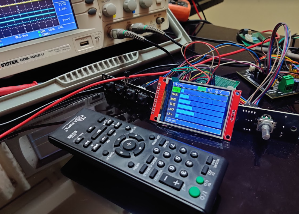
We use the https://github.com/liman324/TDA7419 library to control the IC. We also use the ADAFruit GFX and ILI9341 Libraries. The main issue with ILI9341 was the frequency of communication. A lot of users had complained that the library does not work. If the frequency is set properly the LCD responds correctly.
Arduino pins 8,9,10,11,12,13 are used to interface with the LCD.

#define TFT_CLK 13
#define TFT_MISO 12
#define TFT_MOSI 11

#define TFT_DC 8
#define TFT_RST 9
#define TFT_CS 10

IR Remote is from http://github.com/shirriff/Arduino-IRremote .
Remove uses Arduino pin 2
#define IR_RECV_PIN 2

Encoder library is from https://github.com/mathertel/RotaryEncoder
Encoder uses pins 7 and 5 or Arduino. The encoder push button is mapped to pin 6.
#define ENCODER_PIN_A 7
#define ENCODER_PIN_B 5
#define ENCODER_PIN_SW 6

We use Rectangles to draw the Widgets. There are five different widgets that we can render, all the widgets respond to the key events. To optimize painting only the current focused widget is painted.

More to come…

TDA7419 De-mystified and Secrets revealed. (TDA 7419). Part 1:

TDA7419 is a very powerful IC that can do a lot of things, but since the documentation is very sparse and it even lacks a publicly available application notes. We figured lets take a crack at how we can use it in various use cases. In the following series of posts and videos we will see the various features for TDA 7419. It is primarily designed for Hi-End CAR Audio systems and applications so has very good performance characteristics. This is an ideal candidate for Low-cost Audiophile Digital Input Switchers, Digital Volume Controls, Digital Tone Controls , Mixer for Sub-woofer output etc.

These are the features of TDA 7419

TDA 7419 is basically a hi performance BICMOS Audio Signal processor using the linear signal processing.

It has a Built in Input Selector , You can select from 3 Single Ended Inputs (RCA) or one Quasi Differential Input (Like XLR.) . What is Interesting is that it has TWO Outputs. More on that later.

It has 5 Speaker outputs. Front Left+Right, Rear Left+Right and Sub-Woofer out,

It has a Input Gain Which is useful to Equalize the different Inputs, and a Master Volume control (Attenuator) ,

It has a Powerful Signal processor to control BASS, Mid and Treble Controls. With Selectable Center Frequency and the Q Factor which is basically how wide the Center Frequency Curve is. It has a Separate Loudness Control with Selectable low and high frequency boost and programmable center frequency .

It has a Mixer with LPF and a Sub Woofer output.

It also has a Mixer that allows one input to be Mixed into Front Speakers for Application like a Navigation System output mixing into the main Car Music System.

One Interesting thing about this IC is that it has a whole lot of switchers inside that allow us to customize how the Audio Signal Gets Routed. We can control this IC using I2C.

To control this IC from an MCU , I decided to use arduino there are some projects out there that use PIC too. I wanted to have a Color TFT with a Nice User Interface that would allow me to easily control all the aspects of the IC. I selected a SPI TFT LCD module with ILI9341 controller so I can use the Hardware SPI for LCD and I2C for the TDA7419.

I wanted to have multiple ways to control the UI so there are options for using a Remote , a Push button Interface and a Rotary Encoder with switches. We will go thru all the options in the series.

There are similar projects by others but I could not find a user friendly UI.
https://rcl-radio.ru/?p=57658

The Data sheet is pretty sparse on technical details I also went thru the Arduino Library Source Code at https://github.com/liman324/TDA7419 .

Finally I found the Linux Device driver at https://github.com/torvalds/linux/blob/master/sound/soc/codecs/tda7419.c

This had a lot more information about the internals of the IC and how to almost all of the features that the IC provides.

Why we use a separate MCU instead of RPI GPIO / IR (lircd for rpi).

Our initial plan was to use lirc-rpi (lircd) for Remote and Poll gpio of RPI to
handle the front panel Buttons and rotary Encoder. When we developed the software and looked at the CPU usage we found that polling the GPIO pins frequently for
Buttons and Rotary Encoder and using lircd was taking up decent amount of
CPU cycles. Our design philosophy is always to have as many CPU cycles as possible for audio decoding instead of ancillary tasks. If the audio player
is CPU starved it can lead to degradation of sound quality.
To allow the most CPU headroom for the player , we offload all Input handling tasks like polling Input keys, decoding IR remote etc to a independent MCU board. Since we have a MCU Board that is powered separately, power management and muting also is handled by the MCU.

Reducing Audio Noise During Playback.

When we measured the audio noise during playback we found some
non repeating random noises , when we investigated this , we found
it was from the Ethernet port when the player app was downloading data,
we also noticed noise when using WiFi while streaming data.
We explored various options to reduce it , One to shield it the analog section,
the second would be to reduce as much unnecessary
stuff from running when we are playing back a track. For example
the UPNP server if running answers to any device on the network
querying for it (SSDP).

Our software stack does not run any unnecessary BG daemons till
the user starts it. So unless you are in the UPNP player mode the
daemon is not running in the background. Same for other Player
daemons too.

Second important thing we found that reduced the noise during playback
of network content (NAS/UPNP Stream) or even USB content, is to download it to
a RAM disk and play it from there. There is a small delay during startup for
downloading the track but more than makes up for much better listening
experience. There are No IO operations , no buffering etc, that happen when we playback from the RAM disk so much cleaner sounding playback.
We have an Option to turn on “Download Before Play” in Settings menu.

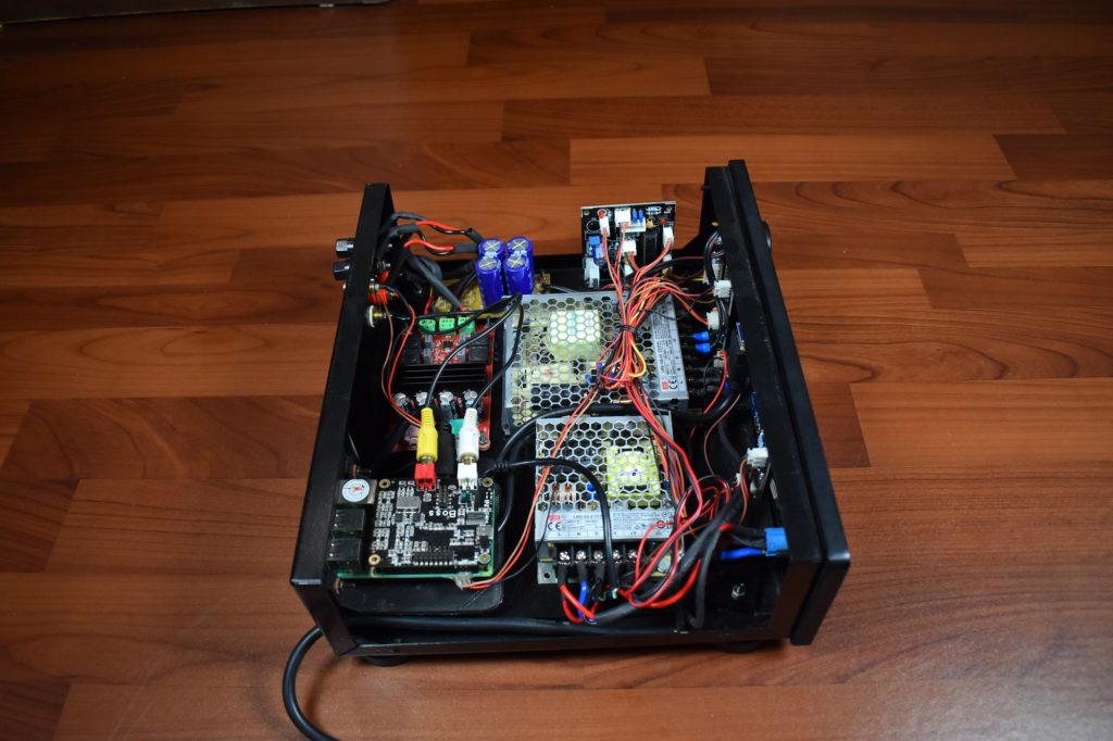
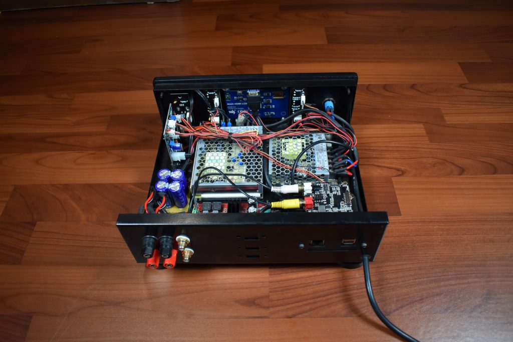
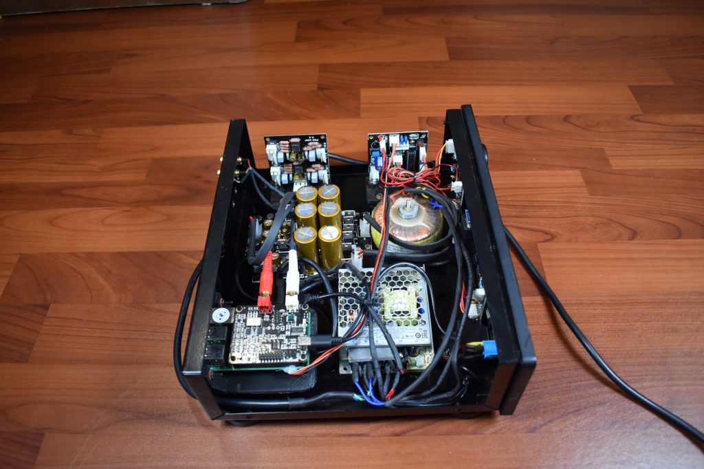
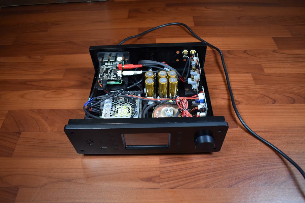
Finally we have taken great care to isolate the power supplies and
shield transformers from analog sections etc.

Pre Amplifier

When we connected just the DAC to power amplifiers , we found that in some cases due to mismatches in impedances’ ,transparency was affected ,some frequencies were attenuated , noise and distortion were also noticed . To alleviate this issue we decided to add a PreAmp between the DAC and the Power amp. We also noticed that when we use the digital volume control in the DAC using the ALSA mixer the control was as smooth and detailed as using an analog volume pot.

We are using two stage amplification using audiophile grade
Burr Brown OPA2134 opamp, resistors and capacitors . The first stage is a fixed gain stage which feeds to the pot this feed the second stage. Since it a dual mono stage we were able to achieve very low cross-talk.

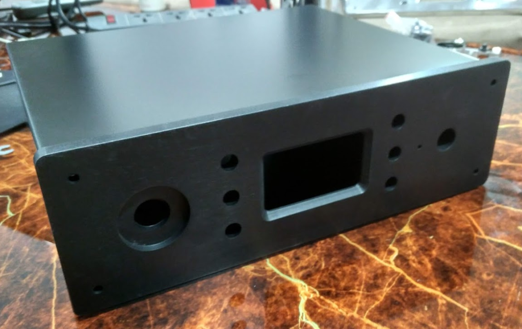
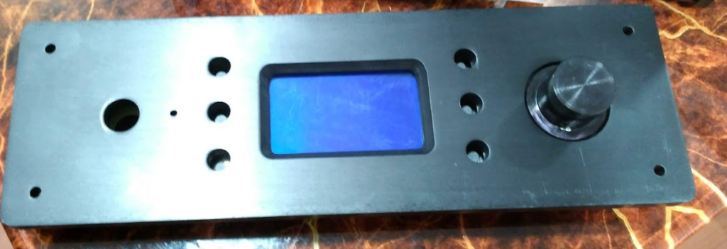
Chassis and Front Pannel

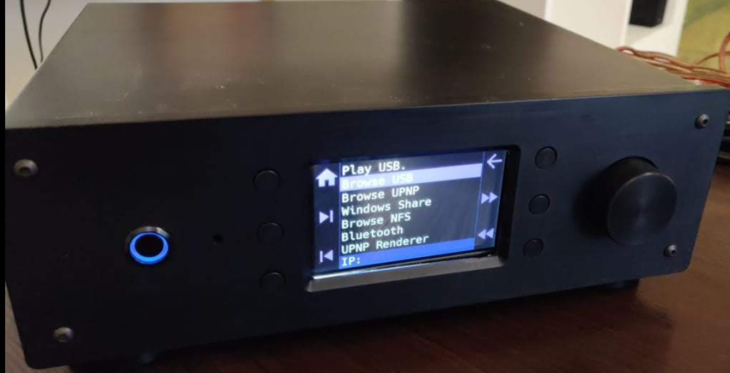
After trying various options we settled on a 10 mm thick aluminium plate for the front panel. The Chassis would be made from 1 mm steel plate. We went thru many iterations to finally settle on the design that everyone liked.

Here are some of the iterations.

Previous Iterations

Sliver Version
Panel with BW LCD
With Monochrome Display
Silver version
Version With Color TFT LCD.

Machined Aluminium Push Buttons

Machined Aluminium Feet
Feet

Machined Aluminium Knobs
Laser Cut Chassis
3D Printed Front Panel USB Holder.
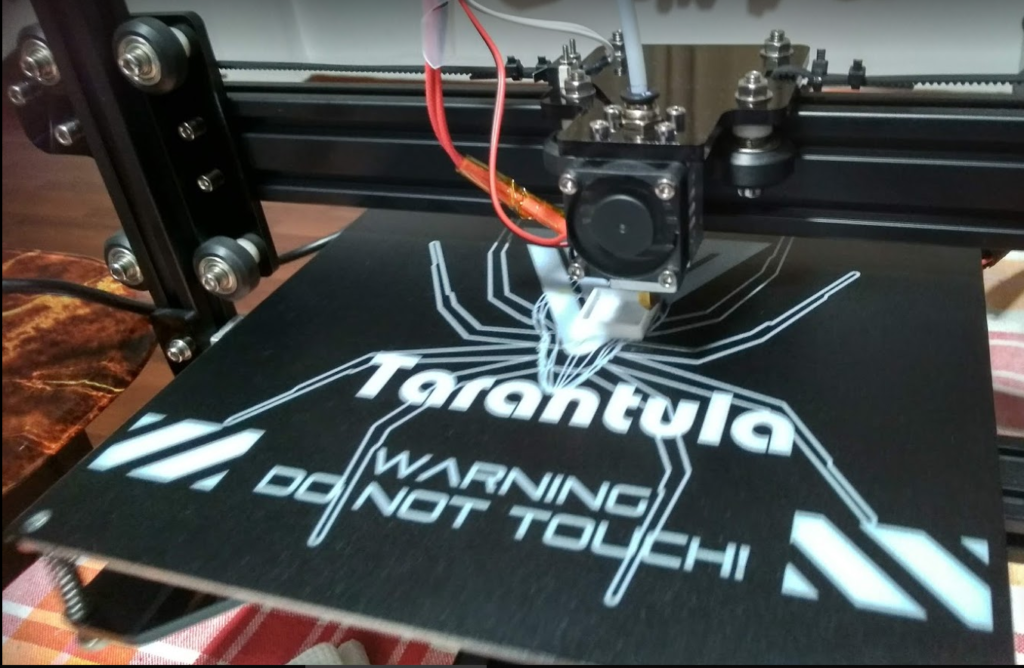
3D Printer for Prototypes
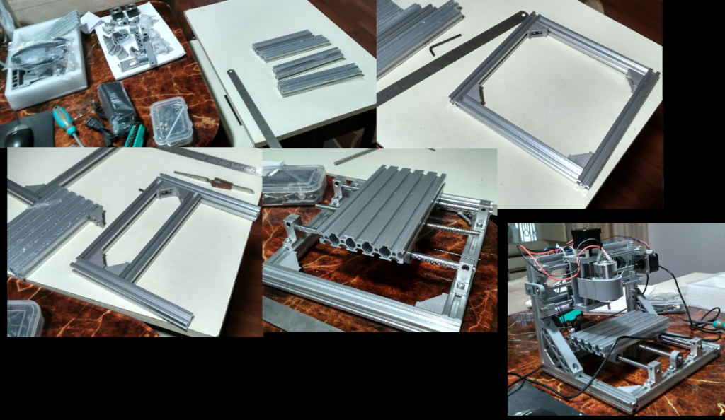
Engraver, for Logo Engraving.